What Is Surface Roughness? An Overview of Ra, Rz, and Rms Values in Engineering
Surface roughness is the fine pattern of microscopic peaks and valleys left on a machined surface, and it is quantified by three main parameters. Ra is the arithmetic average of the profile's deviations from the mean line — the global default. Rz is the average of the five largest peak-to-valley heights — more sensitive to defects. Rms (Rq) is the root-mean-square of the deviations, which weights large peaks more heavily; for the same surface, Rms ≈ 1.11 × Ra and Rz ≈ 4–7 × Ra. Use Ra for general parts, Rz for sealing and fatigue-critical surfaces, and Rms for optics and precision work.
Surface roughness vs. surface finish: these terms are often used interchangeably, but they are not the same. Surface finish is the broader umbrella that also covers processes and treatments such as anodizing, blackening, plating, and bead or sand blasting. This guide is scoped specifically to surface roughness — the geometric texture measured by Ra, Rz, and Rms.
All surfaces have a story to tell. Touch a steel surface that has been ground, then touch a rough-machined one — and the difference is clear right away. In manufacturing, however, feeling alone is not enough; engineers need to measure surface roughness to compare it with the specification and make sure that a part passes quality control.
This is precisely what surface roughness parameters do. And when it comes to those most often used in practice, three stand out above the rest: Ra, Rz, and Rms. They all measure the exact same surface, but each gives you a different picture of its surface quality. Using the wrong parameter can easily give you an acceptable-looking surface in theory, but one that fails in reality.
In this guide, we explore the fundamentals of surface roughness — what it is, how it is determined, what Ra, Rz, and Rms stand for, how they relate to surface roughness grades, what the VDI standards say about textured surfaces, and which one to choose for your engineering drawing.
What Is Surface Roughness, Actually?
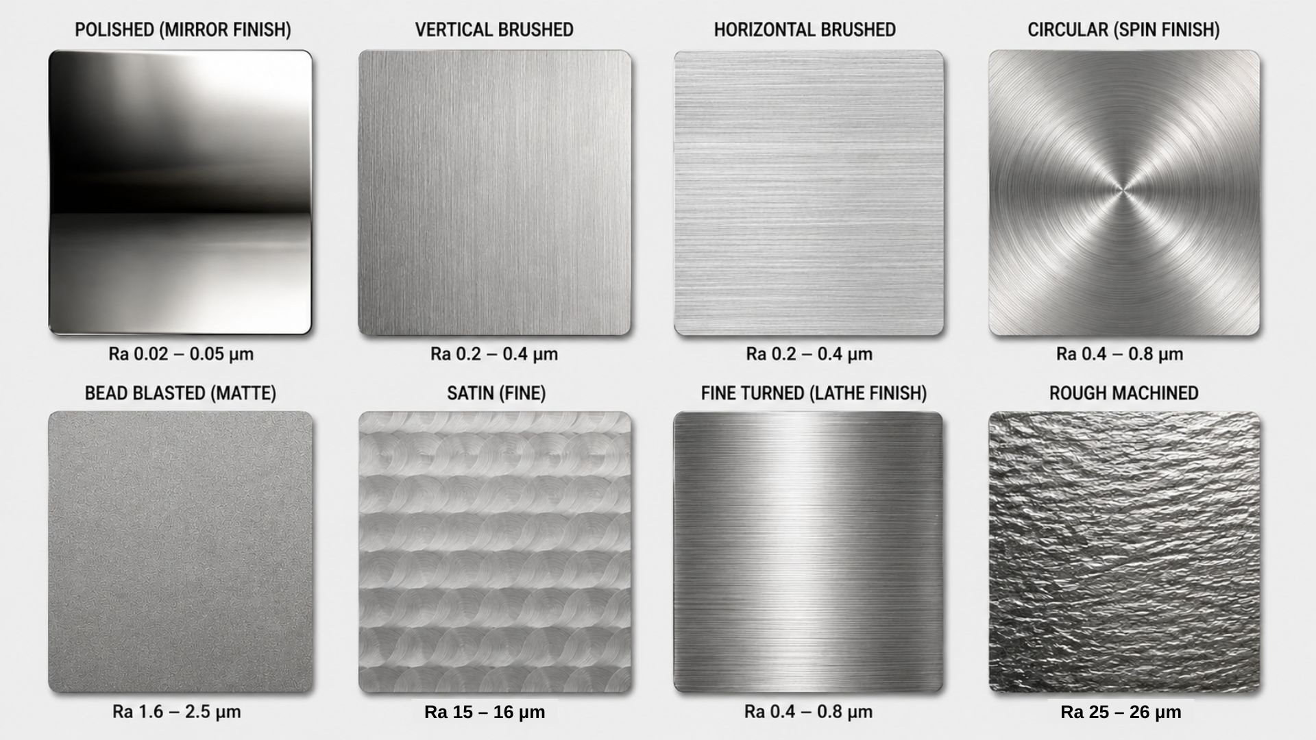
The marks left by the cutting tool as it travels across the material during CNC turning, milling, and grinding constitute a set of microscopic peaks and valleys on the workpiece. This phenomenon — known as surface roughness — can be observed using a specialized profilometer.
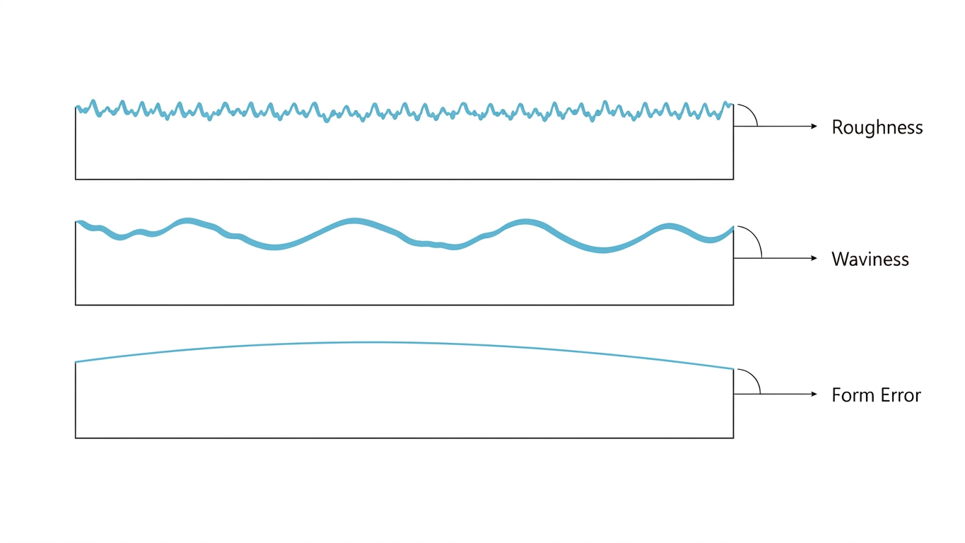
However, there are other kinds of surface deviations. Here is how engineers classify the levels of surface imperfection:
Roughness — the fine peaks and valleys created by the action of the cutting tool (short wavelength)
Waviness — larger ripples produced by vibration, deflection, or other instabilities of the machining process (medium wavelength)
Form error — the deformation of the whole surface of the part, such as bowing and tapering (long wavelength)
Parameters used to determine surface finish — like Ra, Rz, and Rms — quantify the fine surface roughness alone. Surface finish and waviness are distinct terms. In this regard, a surface may be considered roughness-acceptable but waviness-unacceptable.
Why Is Surface Roughness Important in Actual Machining?
Surface roughness is not just a check mark. It affects how parts function during operation. The following aspects depend on the roughness or smoothness of a surface:
Friction and wear — for sliding surfaces such as pistons, shafts, and guide rails, high roughness leads to increased metal-to-metal contact at the peaks. But an excessively smooth surface can also be harmful, as it cannot hold a film of lubricant.
Fatigue strength — the valleys in a rough surface act as stress concentrators. Under cyclic loading, cracks begin precisely from such areas. That is why surface roughness tolerance should be stricter for rotating shafts, connecting rods, and aircraft structural elements.
Sealing capability — gaskets and O-rings cannot follow every valley when pressed onto a rough surface. Each valley is a possible leakage point. Therefore, hydraulic and pneumatic sealing surfaces have tight surface roughness tolerances.
Coatings and adherence — paint, electroplating, anodizing, and powder coating are all affected by the surface finish. If the surface is too smooth, the coating will peel. If it is too rough, the coating won't be able to cover every peak uniformly.
Dimensional accuracy perception — with higher surface roughness, the variability in measuring a dimension increases. A measured length of 25.00 mm may actually vary from 24.97 to 25.03 mm across the peaks and valleys. That is why dimensional tolerance goes hand in hand with surface roughness on drawings.
Measurement of Surface Roughness
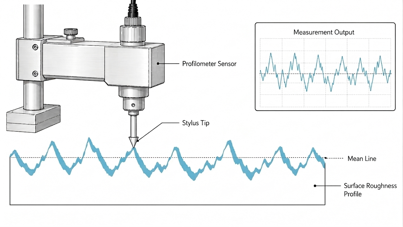
The measurement of surface roughness is carried out with an instrument known as a profilometer. The stylus is dragged over the surface along a specified length and at a specified velocity. As it travels through the peaks and valleys, the upward and downward movement is measured electronically.
Different mathematical equations generate different roughness parameters — Ra, Rz, Rms, Rt, and so forth — from this profile. All of these parameters are generated from the same measurement; the only difference is the equation used to process it.
Today's measurement methods can even include non-contact techniques that use laser triangulation, confocal microscopy, and white light interferometry — ideal for fragile or smooth surfaces that may be damaged by a stylus.
Understanding the Mean Line
In order to define Ra, Rz, and Rms separately, one should first understand the concept of the mean line — since all these characteristics depend on it.
A mean line is a reference line on the surface profile where the total areas above and below it are equal. This line represents an average value of the surface profile. All deviations from it, both peaks and valleys, are counted from the mean line.
As for the evaluation length, over which the roughness is measured, the standard provides for five sampling lengths. This is significant in regard to Rz, as shown below.
Ra — Arithmetic Average Roughness
This is the most commonly used surface roughness parameter in the world. Ra stands for Roughness Average (Arithmetic Mean Roughness) and is defined as the arithmetic mean of all vertical deviations from the mean line over the evaluation length.
Practically speaking, Ra sums all the peak and valley heights (regardless of whether they are positive or negative) and divides them by the total number of values. The result is a single value that shows the average deviation of the surface from perfect planarity.
The measurement unit for Ra is either microns (μm) in the metric system or micro-inches (μin) in the imperial system.
Average Ra for Typical Machining Processes
Machining Process | Range of Average Ra (μm) |
|---|---|
Rough Turning / Rough Milling | 6.3 – 25 |
CNC Turning / Milling | 1.6 – 6.3 |
Fine Turning / Fine Milling | 0.8 – 1.6 |
Grinding | 0.2 – 0.8 |
Honing / Lapping | 0.025 – 0.2 |
Superfinishing / Polishing | 0.01 – 0.1 |
Advantages of Ra
The average roughness height is reliable and predictable. Because it calculates the arithmetic mean of all deviations from the centerline, the presence of a single scratch or abnormally large peak does not significantly alter the Ra value. This makes Ra quite reproducible — take several measurements of the same surface and you will obtain identical or nearly identical Ra values each time.
Disadvantages of Ra
The same averaging that makes Ra reliable is also its major disadvantage. Ra is unable to differentiate two completely different surfaces if they happen to have equal Ra values.
For example, one surface may be characterized by many small peaks with corresponding shallow valleys, while another may consist of a few deep holes and relatively large flat areas. Each of these surfaces could have an Ra value of 1.6 μm, but only the first surface is capable of functioning properly as a seal.
Rz — Average Maximum Height of the Profile
Unlike Ra, Rz does not look at the average value of the profile but pays particular attention to the extreme values. This parameter equals the average of the five maximum peak-to-valley distances across the five equal sampling lengths in the evaluation length.
The calculation goes like this:
Split the evaluation length into five equal sampling lengths.
In each sampling length, determine the highest peak and the lowest valley.
Determine the distance between that peak and that valley (the peak-to-valley height for that section).
Calculate the average of the five peak-to-valley heights.
Because Rz specifically evaluates the maximum height differences in each sampling length, it is much more sensitive to deep scratches, pits, or exceptionally high peaks than Ra is. A single scratch on the surface will significantly increase the Rz value while the Ra might still be quite acceptable.
When to Use Rz Rather Than Ra
It makes sense to use Rz when your application cares about the worst-case roughness profile more than the average. Such circumstances include:
Hydraulic and pneumatic sealing surfaces — one deep valley and your seal will leak.
Fatigue-critical parts — one deep valley will initiate fatigue cracking.
Coatings and platings — one peak higher than the coating thickness and your coating or plating will be broken.
Tight-fitting mating surfaces — one peak may hinder assembly, even though the average roughness meets the requirement.
Europeans and Germans tend to use Rz in preference to Ra because that has historically been the case in Europe/Germany — and so their drawings specify Rz as the default parameter.
Rms — Root Mean Square Roughness
Rms (or Rq according to ISO standards) stands for Root Mean Square roughness. It is similar to Ra in that it is measured over the complete evaluation length — but not in the way it is calculated.
As opposed to Ra, Rms takes the square of each deviation value, averages them, and finally takes the square root of the total:
In this process, large deviations (higher peaks and deeper valleys) have a disproportionate impact on the Rms value compared to Ra. Small deviations have a negligible impact after squaring, while large deviations have a major one. This makes the Rms value always slightly higher than Ra for the same surface. For a typical (near-Gaussian) machined profile the industry rule of thumb is Rms ≈ 1.11 × Ra — roughly 11% higher — though the exact ratio rises as the surface becomes more irregular.
Rms Application Areas
Unlike Ra and Rz, Rms is not commonly used in general mechanical engineering design. It is used where the statistical distribution of surface heights matters more than a simple arithmetic mean:
Optical components (lenses, mirrors, prisms) — surface deviations scatter light, and the energy of the scattered light is proportional to the square of the deviation described by Rms.
Semiconductor wafers and electronics — very strict surface requirements at the nanometre level.
Aerospace and defence — particular standards apply Rms for some critical surfaces.
Research and academia — Rms is mathematically related to the power spectral density of the surface profile, so it is heavily used in tribological studies.
If your drawing does not mention Rms specifically and you are not working in optics or aerospace, Ra should be used.
Roughness Grade Numbers (N1 to N12)
Besides Ra, Rz, and Rms, there is also a simplified classification known as Roughness Grade Numbers, specified according to the ISO 1302 standard.
The N-grade system was designed to make surface roughness specification simpler on drawings — instead of writing "Ra 0.8 μm", a draughtsman could simply mark "N6" on the surface finish symbol.
Complete N-Grade to Ra Conversion Table
Roughness Grade | Ra (μm) | Ra (μin) | Typical Machining Method |
|---|---|---|---|
N1 | 0.025 | 1 | Superfinishing, lapping |
N2 | 0.05 | 2 | Superfinishing, lapping |
N3 | 0.1 | 4 | Lapping, honing |
N4 | 0.2 | 8 | Cylindrical grinding |
N5 | 0.4 | 16 | Fine grinding, honing |
N6 | 0.8 | 32 | Surface grinding |
N7 | 1.6 | 63 | Fine turning, fine milling |
N8 | 3.2 | 125 | CNC turning, CNC milling |
N9 | 6.3 | 250 | General rough turning |
N10 | 12.5 | 500 | Rough milling, sawing |
N11 | 25 | 1000 | Rough casting, forging |
N12 | 50 | 2000 | Heavy rough machining |
In practice, N7 (Ra 1.6 μm) and N8 (Ra 3.2 μm) are the most commonly specified grades for general CNC machined parts. N6 and finer grades are reserved for precision applications and will significantly increase machining cost and time.
Ra vs Rz vs Rms — Direct Comparison
Parameter | Full Name | ISO Symbol | Method of Calculation | Sensitivity to Extremes | Industry Use |
|---|---|---|---|---|---|
Ra | Arithmetic roughness | Ra | Average of the absolute deviations from the mean line | Small — extreme values get averaged out | General mechanical engineering |
Rz | Maximum height | Rz | Average of the peak-to-valley height over 5 sample lengths | Medium — takes the worst case for each section | Sealing, fatigue, coating, European standards |
Rms | Root mean square roughness | Rq | Square root of the mean of the squared deviations | Large — larger deviations get significantly more weight | Optics, aviation, precision instruments |
The ratio between Ra and Rz is not constant. Statistical calculations show that the same Ra can have quite different Rz values because it depends on the real shape of the surface. As an approximate rule of thumb used in industry, Rz is roughly 4 to 7 times greater than Ra on most machined surfaces. However, this is only an estimate and not an exact conversion formula.
VDI 3400 Standards for Surface Roughness on Textured and EDM Surfaces
Apart from Ra, Rz, and Rms, there is another surface classification system that is widely used but rarely understood outside the mold-making and plastic injection industry — the VDI 3400 standard. VDI stands for Verein Deutscher Ingenieure (the Association of German Engineers), and this standard was created specifically to classify textured surface finishes produced through electrical discharge machining (EDM), also known as spark erosion.
Unlike Ra, Rz, or the N-grade system — which were created mainly with conventional machined surfaces in mind — VDI 3400 is built around a completely different kind of surface: one that results from controlled sparking between an electrode and a workpiece, leaving behind a textured, matte, or sometimes deliberately rough pattern rather than a uniformly cut surface.
Why VDI 3400 Exists Separately from Ra and Rz
EDM surfaces behave very differently from milled, turned, or ground surfaces. The texture produced by spark erosion is not made up of regular, repeating tool marks like a milled surface — it is closer to a random, crater-like pattern, since each spark removes a tiny amount of material in an unpredictable location. Because of this randomness, applying standard Ra or Rz measurement directly to an EDM surface does not always give a meaningful or repeatable picture of the texture, especially when the surface is intended to serve a decorative or functional texturing purpose rather than a simple smoothness requirement.
This is exactly the gap that VDI 3400 was designed to fill. Instead of relying purely on Ra, the standard assigns each surface texture a VDI number, ranging typically from VDI 0 (mirror-polished, no visible texture) up to VDI 54 (heavily textured, deep, rough EDM finish). Each VDI number corresponds to an approximate Ra range, giving mold makers, tool designers, and plastic part manufacturers a simple, repeatable way to specify exactly how textured or smooth an EDM-finished cavity surface should be.
VDI 3400 to Ra Approximate Conversion Table
VDI Number | Approximate Ra (μm) | Typical Surface Appearance |
|---|---|---|
VDI 0 | 0.10 – 0.20 | Mirror-polished, no visible texture |
VDI 12 | 0.40 | Very fine textured, slightly matte |
VDI 15 | 0.56 | Fine texture, low gloss |
VDI 18 | 0.80 | Light texture, common for cosmetic mold cavities |
VDI 21 | 1.12 | Medium-light texture |
VDI 24 | 1.60 | Medium texture, semi-matte finish |
VDI 27 | 2.24 | Medium-rough texture |
VDI 30 | 3.20 | Rough textured finish |
VDI 33 | 4.50 | Heavier rough texture |
VDI 36 | 6.30 | Coarse textured surface |
VDI 39 | 9.00 | Very coarse texture |
VDI 42 | 12.50 | Deep textured EDM finish |
VDI 45 | 18.00 | Heavy spark erosion texture |
VDI 48 | 25.00 | Very heavy textured finish |
VDI 51 | 35.00 | Extremely rough texture |
VDI 54 | 50.00 | Maximum standard textured finish |
This conversion is approximate rather than exact, because the relationship between a VDI number and a corresponding Ra value depends on the specific EDM electrode material, the spark settings used during erosion, and even the base material of the mold itself. Two cavities finished to the same VDI number on different EDM machines may show slightly different Ra readings when measured with a profilometer, even though both would be visually and functionally classified under the same VDI grade.
Where VDI 3400 Is Actually Used
VDI 3400 is almost exclusively relevant in industries built around mold tooling and EDM finishing, rather than general CNC machining. Typical applications include:
Plastic injection mold cavities — where the texture on the mold surface transfers directly onto every molded plastic part, making VDI specification critical for matching cosmetic appearance across production runs.
Automotive interior trim molds — dashboard panels, door trims, and similar components rely on a consistent VDI texture to achieve the correct grain pattern and avoid unwanted shine.
Consumer electronics housings — textured plastic housings often specify a VDI grade to control both grip feel and visual finish.
Die-cast tooling — similar texturing requirements apply where a die-cast surface needs a controlled, repeatable finish rather than a polished one.
For an engineer working purely in metal CNC machining, VDI 3400 will rarely appear on a drawing. But for anyone working with injection-molded plastic parts, die-cast components, or any product where the mold cavity finish directly becomes the visible and tactile finish of the final part, understanding VDI 3400 is just as important as understanding Ra, Rz, or Rms.
How VDI 3400 Relates Back to Ra, Rz, and Rms
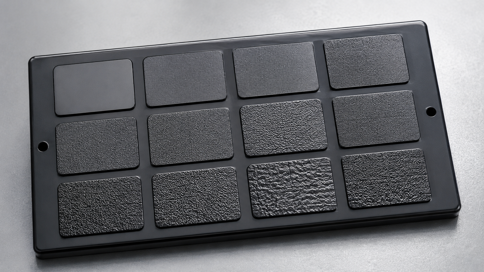
It is worth being clear that VDI 3400 is not a competing or contradictory system to Ra, Rz, and Rms — it is a parallel classification built for a different purpose. While Ra, Rz, and Rms describe the mathematical profile of a surface regardless of how that surface was created, VDI 3400 describes the visual and tactile texture outcome specifically for EDM-finished mold surfaces, expressed in a way that is easy to specify and easy to inspect visually on a sample plaque before full production tooling begins.
In practice, many mold and tooling drawings will specify a VDI number for the cavity texture while separately specifying an Ra value for any non-textured, functional surfaces on the same mold — such as parting lines, sliding cores, or ejector pin locations — where a smooth, low-friction surface is required rather than a textured one. Both systems often appear side by side on the same tooling drawing, each covering a different category of surface on the same component.
Frequently Asked Questions
What is the difference between Ra, Rz, and Rms?
Ra is the arithmetic average of all profile deviations from the mean line, so it smooths out individual extremes. Rz is the average of the five largest peak-to-valley heights across the evaluation length, so it captures the worst-case features. Rms (Rq) is the root mean square of the deviations, which gives larger peaks and valleys extra weight. All three are measured from the same profile — only the math differs.
How do you convert Ra to RMS?
For a typical machined surface, multiply Ra by about 1.11 — Rms is roughly 11% higher than Ra (Rms ≈ 1.11 × Ra). This is an approximation valid for near-Gaussian profiles; very irregular surfaces deviate from it, so it should not be used for safety-critical specifications.
What is the relationship between Ra and Rz?
There is no exact conversion, because two surfaces with the same Ra can have very different Rz values depending on their actual shape. As a shop rule of thumb, Rz is approximately 4 to 7 times Ra for normal production machining. If the measured Rz/Ra ratio is much higher than 7, the surface likely has isolated deep scratches or tool marks that Ra is averaging out.
What is a 125 surface finish?
A "125" callout means Ra 125 micro-inches, which equals Ra 3.2 μm and corresponds to roughness grade N8. It is a common general-machining finish for non-critical surfaces produced by standard CNC turning or milling.
Should I specify Ra or Rz on a drawing?
Use Ra for general-purpose parts where an average, reproducible value is sufficient — it is the global default and the standard in North American practice (ASME B46.1). Use Rz when peak height is functionally critical: sealing surfaces, fatigue-loaded parts, coatings and platings, and tight mating fits. Rz is also the common default on European and German drawings (ISO 4287 / ISO 21920).
Is surface roughness the same as surface finish?
No. Surface roughness refers specifically to the fine geometric texture measured by parameters like Ra, Rz, and Rms. Surface finish is a broader term that also includes surface treatments and coatings such as anodizing, blackening, plating, and bead or sand blasting. Every surface roughness value describes a surface finish characteristic, but not every surface finish requirement is about roughness.
Conclusion
Surface roughness is one of those parameters that is quietly stated in engineering drawings yet is crucial to the performance, durability, and manufacturing cost of a part.
If you need an accurate, repeatable value that suits most machined parts, Ra provides one.
If you need the utmost control over worst-case surface conditions, use Rz.
For optics, semiconductors, and other precision parts, the statistical accuracy of Rms is your choice.
And if you are working with injection molds or EDM-finished tooling, VDI 3400 gives you a practical way to specify and inspect textured surfaces that none of the other three parameters were really built to describe.
Knowing how Ra, Rz, Rms, and VDI 3400 differ — not just through their abbreviations, but through their actual meanings and purposes — is what allows engineers to create drawings that are both manufacturable and functional. The next time you see a surface finish specification, you will know what those numbers actually mean and why they were selected.