CNC Machining Tolerances: Types and How to Specify
CNC machining tolerance is the permitted variation on a dimension. The range between upper and lower limits inside which a machined feature is acceptable. Two parts can look identical on nominal size and still differ sharply in cost, lead time, and inspectability depending on how tightly you specify. For most outsourced CNC work, general tolerances (often ISO 2768-mK) cover non-critical dimensions; reserve tight callouts (±0.01 mm, ISO 286 fits such as H7/g6, or GD&T frames) only where fit, location, or function truly needs them.
Scope note: This guide is for B2B procurement officials and manufacturing / mechanical engineers who specify tolerances on precision CNC machined parts. It covers tolerance types, ISO 2768 and ASME standards, ISO 286 hole/shaft fits, tolerance stack-up, process and material capability, cost impact, inspection, and specification rules. It is not a full GD&T or ISO 286 handbook. For complete ISO 2768 lookup tables, see our ISO 2768 Tolerance Charts.
Every CNC part carries an invisible but decisive drawing feature: tolerance. Identical nominal dimensions can produce totally different quotes, scrap rates, and functional outcomes depending on how variation is allowed. This guide covers what tolerance means in CNC practice, the main expression types, machine vs design tolerance, common standards, typical process ranges, materials, fits, stack-up, cost impact, and practical rules for specifying on drawings before you send an RFQ.
What Is Tolerance in CNC Machining?
Tolerance is the allowed deviation from a nominal dimension. No machined feature is mathematically perfect: tool wear, heat, material behavior, vibration, and machine limits all introduce variation. Tolerance defines how much variation is acceptable before a part is non-conforming. Each toleranced dimension has an upper limit and a lower limit. Measurements inside that band conform; outside it, the feature fails, regardless of how close the nominal looks on paper.
Example: a hole called 20 mm ±0.1 mm is acceptable from 19.9 mm to 20.1 mm. Narrow that band and you raise precision, machining time, inspection load, scrap risk, and cost. Widen it and you cut cost but risk fit or function if variation exceeds what the assembly can absorb. The goal is the loosest band that still guarantees function.
What Are the Two Meanings of "Tolerance" in CNC?
The word tolerance is used in two distinct ways on CNC jobs. Confusing them is a common source of over-specification and quote mismatch.
Machine tolerance (process capability)
Machine tolerance is what a given CNC process can reliably hold. The shop’s or machine’s dimensional capability under normal conditions.
High-end machining centers under ideal conditions can hold features near ±0.0025 mm on favorable geometry.
Typical production milling/turning on standard features often lands around ±0.02 mm to ±0.05 mm.
Tighter bands on critical features are possible when the process is deliberately set up for them, but that is not automatic on every feature, material, or machine. Machine tolerance describes capability, not what you should blindly print on every dimension.
Design tolerance (functional requirement)
Design tolerance is what the engineer assigns on the drawing based on fit, form, and function, not on what is easy to cut.
A bearing bore or shaft journal needs a tight design tolerance because mates depend on it.
Overall length on a bracket with no mating interface can use a looser general tolerance.
Rule of thumb: design tolerance must be achievable within the machine tolerance of the process you intend to use. Specifying ±0.005 mm on every face when the process and material cannot hold it drives scrap, secondary grinding, or an unmakeable RFQ.
What Types of Tolerances Appear on CNC Drawings?
Different notation styles communicate intent to the machinist and inspector. These are the types you will see and specify most often.
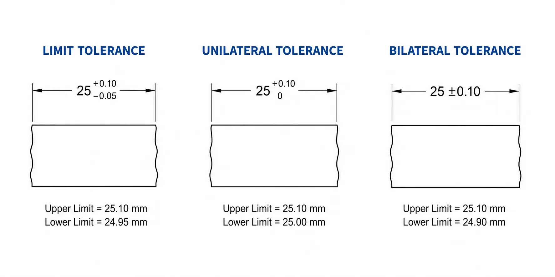
Limit tolerances
Limit tolerance states explicit upper and lower bounds instead of nominal ± deviation. Example: 12.45 mm – 12.55 mm. Any measurement in that range conforms. Limit tolerances are common for fits and clearances (shaft/hole pairs) because the acceptable window is stated directly without mental math.
Unilateral tolerance
Unilateral tolerance allows deviation in one direction only from nominal. Example: 25 mm +0.05 / −0.00. The feature may be up to 25.05 mm but not below 25.00 mm. Use when one-sided variation matters more, e.g. a hole that must not undersize for a fastener but may be slightly larger.
Bilateral tolerance
Bilateral tolerance allows deviation in both directions, equal or unequal.
Style | Example | Resulting band |
|---|---|---|
Equal bilateral | 40 mm ±0.1 mm | 39.9 – 40.1 mm |
Unequal bilateral | 40 mm | 39.95 – 40.15 mm |
Equal bilateral is the most common general mechanical notation because it is quick to read and symmetric around nominal.
Geometric Dimensioning and Tolerancing (GD&T)
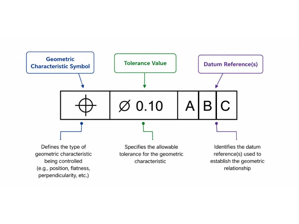
GD&T controls shape, orientation, location, and runout, not just size. It is defined under ASME Y14.5 (common in the USA) and ISO 1101 (international). Where ± size tolerances say how big a hole may be, GD&T can require that hole’s axis be perpendicular to a datum within a stated zone, or that a surface stay flat within a limit.
Category | Characteristics covered |
|---|---|
Form | Flatness, straightness, circularity, cylindricity |
Orientation | Perpendicularity, parallelism, angularity |
Location | Position, concentricity, symmetry |
Profile | Profile of a line, profile of a surface |
Runout | Circular runout, total runout |
GD&T appears in feature control frames on the drawing: symbol, tolerance value, and datum references. Use GD&T when the relationship between features matters, not just their size.
What General Tolerance Standards Should You Use?
Most CNC drawings do not tolerance every dimension individually. A general tolerance note in the title block applies to all dimensions unless overridden. See full tables in ISO 2768 Tolerance Charts.
ISO 2768 (international)
ISO 2768 is the most widely used general tolerance system in mechanical engineering.
ISO 2768-1: linear and angular tolerances; classes f (fine), m (medium), c (coarse), v (very coarse)
ISO 2768-2: geometrical tolerances; classes H, K, L
ISO 2768-mK (medium linear + K geometry) is a common default on general-purpose CNC parts: accurate enough for most brackets and housings without over-constraining every edge.
Nominal dimension range (mm) | ISO 2768-1 medium (m) ± (mm) |
|---|---|
0.5 to 3 | ±0.1 |
Over 3 to 30 | ±0.2 |
Over 30 to 120 | ±0.3 |
Over 120 to 400 | ±0.5 |
Over 400 to 1000 | ±0.8 |
Notice how the band widens as the feature gets larger. Holding a 5 mm bore to ±0.1 mm is a different problem from holding a 300 mm length to the same number. Bigger parts move more with heat and clamping, so the standard gives them more room. For legacy German drawings, see how DIN 7168 maps to ISO 2768 in DIN 7168 vs ISO 2768.
ASME Y14.5 (North America)
ASME Y14.5 is the US dimensioning and tolerancing standard that underpins GD&T practice for aerospace, defense, automotive, and many American OEM supply chains. It integrates dimensional and geometric rules in one framework: complementary to, not a drop-in replacement for, ISO 2768 general tolerance callouts. Practical split: many European drawings lead with ISO 2768-mK; many US aerospace/defense drawings lean on ASME Y14.5 / GD&T on critical interfaces. Know which your customer or internal standard expects before you mix notations.
What Tolerances Can CNC Processes Typically Hold?
Achievable bands depend on machine, material, geometry, and fixturing, but these ranges are useful when setting design tolerance to match process capability:
CNC process | Typical achievable tolerance |
|---|---|
CNC milling (general features) | ±0.05 mm to ±0.1 mm |
CNC milling (tight features) | ±0.01 mm to ±0.025 mm |
CNC turning (general) | ±0.025 mm to ±0.05 mm |
CNC turning (precision) | ±0.005 mm to ±0.01 mm |
CNC drilling | ±0.05 mm to ±0.1 mm |
Wire EDM | ±0.005 mm to ±0.01 mm |
CNC grinding | ±0.0025 mm to ±0.005 mm |
Honing / lapping | Often ±0.001 mm to ±0.005 mm (or finer) |
If your drawing demands grinding-level tolerance on a feature that will only be milled, expect either a rejected quote, a process change, or a large cost adder.
How Do Materials Affect Achievable Tolerances?
Copying the same tight band from an aluminum prototype onto titanium or hardened steel is a common buyer mistake. Material behavior changes how hard (and expensive) a given tolerance is to hold.
Material family | Tolerance behavior for buyers |
|---|---|
Aluminum alloys | Usually the most forgiving for tight bands; low cutting forces, clean chip. Watch thermal expansion on large parts measured warm vs cold. |
Mild / carbon steel | Reliable under normal conditions; slightly higher cutting forces than aluminum on slender features. |
Stainless steel | Work-hardens if the tool dwells; needs consistent feed, sharp tools, and good coolant to hold the same band as aluminum. |
Titanium / nickel alloys | High heat and tool wear; same numeric tolerance often needs slower cycles, more tool changes, and higher scrap risk. |
Soft / gummy alloys and some plastics | Harder to hold extreme bands than rigid steels; ask whether the material can sustain the callout at production quantity. |
When you change material on a reused drawing, re-check critical tolerances with the supplier before you freeze the RFQ.
What Are ISO 286 Hole and Shaft Fits?
When a shaft must run, locate, or press into a bore, inventing bilateral ± values on both parts is slow and error-prone. ISO 286 (limits and fits) gives standard hole/shaft combinations shops worldwide already understand. Capital letters (e.g. H7) describe the hole; lowercase (e.g. g6) describe the shaft. The letter sets where the tolerance zone sits relative to nominal; the number is the IT grade (smaller number = tighter band).
Fit type | What you get | Common callouts | Typical use |
|---|---|---|---|
Clearance | Shaft always smaller than hole | H7/g6, H7/h6, H8/f7 | Sliding / running fits, guides |
Transition | Clearance or light interference depending on actual sizes | H7/k6, H7/n6 | Locating pins, light press assemblies |
Interference | Shaft always larger than hole | H7/p6, H7/r6, H7/s6 | Press-fit bearings, hubs, permanent joints |
Hole-basis fits (H on the hole) are the usual default because fixed hole tooling (reamers, boring) is standardized and the shaft is adjusted on the lathe. Writing Ø25 H7/g6 communicates the functional relationship without calculating both bilateral bands by hand. Use ISO 286 on mating cylindrical features; keep ISO 2768 for everything else that is not a defined fit.
What Is Tolerance Stack-Up?
Tolerance stack-up is the accumulation of individual feature (or part) tolerances along an assembly chain. Each piece can be in spec and the assembly can still fail if worst-case extremes add up.
Simple example: three spacers, each 20 mm ±0.1 mm, in a housing 60.5 mm ±0.2 mm.
Worst case long: spacers at 20.1 mm each (60.3 mm total) vs housing at minimum 60.3 mm → zero clearance; assembly may not close.
Worst case short: spacers at 19.9 mm each → large gap.
Fix stack-up in design, not at incoming inspection:
Identify the closing dimension that must work (gap, interference, alignment).
List every contributor on that chain.
Tighten only the few features that dominate the stack; leave the rest on general tolerance.
Prefer standard ISO 286 fits on cylindrical mates instead of ad-hoc ± on both sides.
Tightening every dimension “to be safe” is the expensive way to fix a stack problem that two or three critical callouts would solve.
How Do Tight Tolerances Affect CNC Part Cost?
Every tolerance band tighter than function requires adds real machine time, inspection, and risk. Vanity tightness is one of the fastest ways to inflate a CNC quote. Specifying too loose on critical features is the other failure mode: cheap parts that do not assemble or fail in the field.
Tolerance specified | Relative cost impact | Why |
|---|---|---|
±0.1 mm (standard general) | Baseline | Normal feeds, standard setup, routine inspection |
±0.05 mm | +5% to +15% | Slower feeds, more in-process checks |
±0.025 mm | +15% to +30% | Finishing passes, tighter fixturing, more measurement |
±0.01 mm | +30% to +60% | Often CMM verification, precision fixtures, lower feeds |
±0.005 mm and tighter | +60% or more | Grinding/specialized equipment, controlled conditions, high scrap risk |
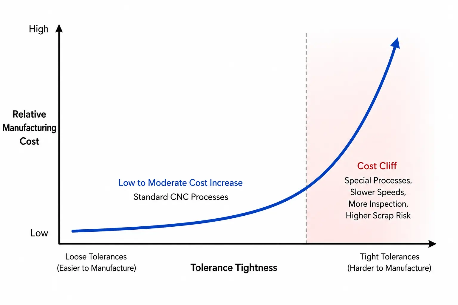
Too tight: longer cycle time, faster tool wear, more rejects, longer lead time, and sometimes borderline parts that pass inspection but perform poorly. Only a small share of features on a typical part need precision bands.
Too loose on critical features: bearing that should press slides free; seal that should seal leaks; bolt pattern that will not align. Field failures and recalls cost far more than the machining premium you avoided.
Selective precision is the buyer rule: tight where function demands it, standard everywhere else. On Sattardas, tolerance is a selectable parameter on the instant quote flow, so you see how tightening a band moves price and lead time on your geometry before you lock the drawing, instead of discovering the premium after a week of email RFQ.
How Does Inspection Change With Tighter Tolerances?
The method needed to prove a tolerance is part of what you buy.
Tolerance band (typical) | Common verification | Buyer implication |
|---|---|---|
~±0.05 mm to ±0.1 mm | Calipers, micrometers, bore/ring gauges | Fast, low cost on the floor |
~±0.01 mm to ±0.05 mm | Precision hand tools and/or CMM | More time; may need programmed inspection |
Below ~±0.01 mm, or GD&T position/orientation | CMM, optical, or specialized metrology | Higher cost and lead time per part certified |
If you specify a band that requires CMM or FAIR documentation, you are buying that inspection path on every certified piece. Justify it on critical features; do not require it on non-critical faces that hand gauges could clear.
How Should You Specify Tolerances on CNC Drawings?
Identify functional features first: Mating faces, bearing seats, sealing surfaces, locating pins/holes, sliding fits, and critical threads.
Set the loosest band that still works: Use ISO 286 fits (e.g. H7/g6) for cylindrical mates; use explicit ± or GD&T only where the fit system does not apply.
Apply a general tolerance to everything else: e.g. ISO 2768-mK in the title block. Without it, unmarked dimensions become a dispute at inspection.
Check stack-up on assemblies: Tighten only the contributors that drive the closing dimension.
Do not tighten “to be safe”: Blanket ±0.01 mm on every edge raises cost and scrap without adding function. Match tolerance to function, a core DFM principle in our Design for Manufacturing (DFM) Guide.
Match tolerance to material and process: Confirm the alloy and the intended process (mill, turn, grind, EDM) can hold the band at production quantity.
Confirm supplier capability and inspection path: For outsourced CNC, verify the partner can hold and measure your critical callouts before you freeze the drawing.
Use GD&T when relationships matter: If position, orientation, or form control assembly quality, ± size alone is insufficient.
Align drawing and 3D model: STEP vs PDF mismatches on tolerance force clarification loops that delay production. See How to Reduce CNC Lead Time.
Ask for a DFM / manufacturability review before release when the part is new or the tolerances look aggressive relative to size and material.
How Sattardas Helps You Specify and Quote Tolerances
Sattardas is an on-demand precision CNC platform with instant quotations. Upload a STEP file, get price and DFM feedback in minutes, manufactured in India and delivered DAP to your door in Europe and the USA. You select general or tight tolerance bands there (down to precision levels such as ±0.005 mm on applicable features), along with material, finish, and inspection, so achievable tolerance, cost, and lead time are visible before you commit. That lets engineers and procurement test whether a tighter callout is worth the premium on the actual part, instead of defaulting to over-specification or accepting a surprise invoice after manual quoting. CMM reports and related inspection options can be configured in the same flow when critical features need documented proof.
Frequently Asked Questions
What is the tightest tolerance a standard CNC shop can hold?
Under ideal conditions, high-precision equipment can approach ±0.0025 mm on favorable features. That is not typical for everyday milled parts. Most production CNC work lives in the ±0.02 mm to ±0.1 mm range unless a feature is deliberately set up for precision, or sent to grinding/EDM.
Do I need to tolerance every dimension on a drawing?
No. Tolerance only dimensions that affect mate, location, or performance. Use a general tolerance note (e.g. ISO 2768-mK) in the title block for everything else. Over-dimensioning every edge is a common cause of unnecessary cost.
What is the difference between machine tolerance and design tolerance?
Machine tolerance is what the process can achieve. Design tolerance is what you require for function. Design tolerance must fit inside realistic machine capability, or you need a different process, material, or supplier.
Why do tight tolerances increase CNC cost?
Tighter bands force slower feeds, more careful fixturing, more measurement, higher scrap on borderline parts, and sometimes secondary operations. Each step adds spindle time and inspection time, which shows up directly in unit price and often in lead time.
What is an H7/g6 fit?
H7/g6 is a common ISO 286 clearance (sliding) fit. H7 sets the hole tolerance zone; g6 sets the shaft. Together they produce a small, predictable clearance for free assembly and controlled motion. Prefer standard fit callouts on cylindrical mates instead of inventing bilateral ± on both parts.
What is tolerance stack-up and when should I check it?
Tolerance stack-up is the sum of individual tolerances along an assembly chain. Check it whenever multiple parts determine a gap, interference, or alignment. Parts can all be in spec and still fail to assemble if worst-case extremes add up.
Does material choice change what tolerances I can specify?
Yes. Aluminum is usually the most forgiving for tight bands. Stainless, titanium, and hardened steels often need more process control (and cost) to hold the same numbers. Re-validate tolerances when you change material on a reused drawing.
Should I use ISO 2768 or ASME Y14.5?
ISO 2768 (often -mK) is the default general tolerance system for much international mechanical work. Use our ISO 2768 Tolerance Charts for full values. ASME Y14.5 is central to GD&T practice in North American aerospace, defense, and automotive supply chains. Many drawings use ISO 2768 for general limits, ISO 286 for hole/shaft fits, and GD&T frames on critical interfaces; follow your customer’s drawing standard.
How can I see what my tolerance choice costs before ordering?
Upload your STEP file to a platform that prices tolerance as a parameter. On Sattardas, changing the tolerance band on the instant quote updates price and lead time in real time, so you can compare standard vs tight specification on the same geometry.
Conclusion
CNC tolerance drives fit, cost, inspectability, and lead time. Use ISO 2768 (typically -mK) for the bulk of a part, ISO 286 fits for cylindrical mates, explicit tight callouts and GD&T only on functional interfaces, and check stack-up before you release multi-part assemblies. Match bands to material and process capability, and buy only the inspection path the critical features need. Specifying right the first time is cheaper than rework, scrap, or a quote that doubles when the shop reads your drawing honestly.